John Deere 250GR Hydraulic Excavator Technical Manual VOL 3 OF 5 (TM1214A-IN2-3)
TABLE OF CONTENTS
SAFETY RELIEF VALVE TEST.
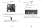
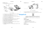
Figure I. Safety Relief Valve Setup
Figure 2 Fuel Injector Supply Lines
Figure 3. Pipe Adaptors and Elbow Setup
Figure 4. Test Setup
Figure 5. Fuel Injector Supply Lines
Figure 6. Hose and Container
Figure 7. Fuel Injector Supply Lines
Figure 8. Test Setup
Figure 9. Pipe Adaptors and Elbow Setup
Figure IO. Safety Relief Valve Setup
Figure II. Fuel Injector Supply Lines
SERVICE ADVISOR CYLINDER ELECTRONIC COMPRESSION TEST
Figure 1. Readings and Connect to Model(s)
Figure 2. Readings Adaptec
Figure 3. Connection Type
Figure 4. Tests and Calibrations in Service ADVISOR
Figure 5. ECIJ – Engine Serial Number in Service ADVISOR
Figure 6. Cylinder Electronic Compression Test in Service ADVISOR
Figure 7. Cylinder Electronic Compression Test Successful Part 1 in Service ADVISOR
Figure 8. Cylinder Electronic Compression Test Successful Patt 2 in Service ADVISOR
Figure 9. Readings and Disconnect From Model(s)
Figure 10. Terminate
SKILLED BASED APPROACH FOR DIAGNOSTIC TROUBLESHOOTING
Figure 1. Set Multimeter to Measure Continuity/Resistance

")
")
")
")