
-13%


Format: PDF
Language: EN
File Size: 21.89 MB
Pages: 701
Printable Content
$40 Original price was: $40.$35Current price is: $35.
GENERAL
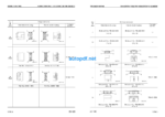
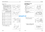
SPECIFICATION DRAWINGS
FUEL, COOLANT AND LUBRICANTS
PTO
PTO LUBRICATION SYSTEM
POWER TRAIN SWING MACHINERY SWING CIRCLE
FINAL DRIVE
TRACK FRAME AND RECOIL SPRING
IDLER CARRIER ROLLER
TRACK ROLLER
TRACK SHOE ( 1/ 2)
( 2/ 2)
MOTOR GREASE PUMP
HYDRAULIC TANK
HYDRAULIC PUMP
LINE OIL FILTER
PILOT OIL FILTER
DRAIN OIL FILTER
L. H. 5- SPOOL CONTROL VALVE
R. H. 4- SPOOL CONTROL VALVE
STRAIGHT- TRAVEL VALVE
SWING MOTOR
CENTER SWIVEL JOINT
TRAVEL MOTOR
PPC CONTROL RELIEF VALVE
SAFETY LOCK VALVE
PPC ACCUMULATOR
VALVE CONTROL
WORK EQUIPMENT, SWING PPC VALVE
TRAVEL PPC VALVE
SOLENOID VALVE
HYDRAULIC CYLINDER
WORK EQUIPMENT
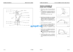
DIMENSIONS OF WORK EQUIPMENT
AIR CONDITIONER
ENGINE CONTROL
MACHINE CONTROL SYSTEM
MONITOR SYSTEM
SENSORS
TESTING AND ADJUSTING
STANDARD VALUE TABLE FOR ENGINE
STANDARD VALUE TABLE FOR CHASSIS
STANDARD VALUE TABLE FOR ELECTRICAL PARTS
TOOLS FOR TESTING, ADJUSTING, AND TROUBLESHOOTING
MEASURING AIR SUPPLY PRESSURE ( BOOST PRESSURE)
MEASURING EXHAUST TEMPERATURE
MEASURING EXHAUST COLOR
ADJUSTING VALVE CLEARANCE
MEASURING BLOW- BY PRESSURE
MEASURING COMPRESSION PRESSURE
MEASURING ENGINE OIL PRESSURE
HANDLING EQUIPMENT IN FUEL CIRCUIT
RELEASING REMAINING PRESSURE IN FUEL SYSTEM
MEASURING FUEL PRESSURE
REDUCED CYLINDER MODE OPERATION FOR ENGINE
BLEEDING AIR FROM FUEL CIRCUIT
CHECKING FOR LEAKAGE IN FUEL CIRCUIT
TESTING AND ADJUSTING ALTERNATOR BELT TENSION
TESTING AND ADJUSTING FAN BELT TENSION
TESTING AND ADJUSTING AIR CONDITIONER COMPRESSOR DRIVE BELT TENSION
HANDLING ENGINE CONTROL- LER HIGH VOLTAGE CIRCUIT
ADJUSTING ENGINE SPEED SENSOR
TESTING AND ADJUSTING HYDRAULIC PRESSURE IN WORK EQUIPMENT, SWING, TRAVEL CIRCUIT
TESTING AND ADJUSTING CONTROL PUMP CIRCUIT OIL PRESSURE
TESTING AND ADJUSTING PISTON PUMP CONTROL PRESSURE
MEASURING SERVO PISTON STROKE
MEASURING PPC VALVE OUT- PUT PRESSURE
TESTING SOLENOID VALVE OUTPUT PRESSURE
ADJUSTING WORK EQUIP- MENT, SWING PPC VALVE
TESTING TRAVEL DEVIATION
TESTING LOCATIONS CAUSING HYDRAULIC DRIFT OF WORK EQUIPMENT
MEASURING OIL LEAKAGE
TESTING CLEARANCE OF SWING CIRCLE BEARING
TESTING AND ADJUSTING TRACK SHOE TENSION
BLEEDING AIR
RELEASING REMAINING PRESSURE IN HYDRAULIC CIRCUIT
PROCEDURE FOR CHECKING DIODE
POINTS TO REMEMBER WHEN TROUBLESHOOTING
SEQUENCE OF EVENTS IN TROUBLESHOOTING POINTS TO REMEMBER WHEN CARRYING OUT MAINTENANCE CHECKS BEFORE TROUBLESHOOTING
CONNECTOR TYPES AND MOUNTING LOCATIONS
CONNECTION TABLE FOR CONNECTOR PIN NUMBERS
EXPLANATION OF CONTROL MECHANISM FOR ELECTRICAL SYSTEM
DISPLAY METHOD AND SPECIAL FUNCTIONS OF MONITOR PANEL
METHOD OF USING JUDGEMENT TABLE
METHOD OF USING TROUBLESHOOTING CHARTS
DETAILS OF TROUBLESHOOTING AND TROUBLESHOOTING PROCEDURE
ACTION TAKEN BY CONTROLLER WHEN ABNORMALITY OCCURS AND PROBLEMS ON MACHINE
N- 1 [ E117, E118 occur at same time ] Monitor panel communication abnormality
N- 2 [ E117, E218 occur at same time ] Engine controller communication abnormality
N- 3 [ E118, E955 occur at same time ] Pump controller communication abnormality
ACTION TAKEN BY CONTROLLER AND CONDITION OF MACHINE WHEN ERROR CODE IS DISPLAYED
ACTION TAKEN BY CONTROLLER AND CONDITION OF MACHINE WHEN ERROR CODE IS DISPLAYED
E- 1 [ E91b ] ( Abnormality in engine speed Ne sensor system) is displayed
E- 2 [ E91C ] ( Abnormality in engine G rotation sensor system) is displayed
E- 3 [ E920 ] ( Abnormality in model selection system) is displayed
E- 4 [ E922 ] ( Engine overrun) is displayed
E- 5 [ E924 ] ( Drop in engine oil pressure) is displayed
E- 6 [ E931 ] ( Abnormality in fuel control dial sensor system) is displayed
E- 7 [ E934 ] ( Abnormality in engine water high- temperature sensor system) is displayed
E- 8 [ E936 ] ( Abnormality in engine oil pressure switch system) is displayed
E- 9 [ E93C ] ( Abnormality in boost pressure sensor system) is displayed
E- 10 [ E93d ] ( Abnormality in fuel temperature sensor system) is displayed
E- 11 [ E954 ] ( Short circuit in starting switch C system) is displayed
12 [ E955 ] ( Abnormality in network system) is displayed
E- 13 [ E956 ] ( Power source system abnormality 1) is displayed
E- 14 [ E957 ] ( Power source system abnormality 2) is displayed
15 [ E95A ] ( Abnormality in fuel injection amount adjustment switch signal) is displayed
E- 16 [ E96A ] ( Abnormality in engine water low- temperature sensor system) is displayed
E- 17 [ E970 ] ( Excess current in fuel supply pump PCV1 system) is displayed
E- 18 [ E971 ] ( Excess current in fuel supply pump PCV2 system) is displayed
E- 19 [ E974 ] ( Disconnection in fuel supply pump PCV1 system) is displayed
E- 20 [ E975 ] ( Disconnection in fuel supply pump PCV2 system) is displayed
E- 21 [ E977 ] ( Abnormality in common rail fuel pressure sensor system) is displayed
E- 22 [ E979 ] ( Common rail fuel high pressure abnormality 1) is displayed [ E97A ] ( Common rail fuel high pressure abnormality 2) is displayed
E- 23 [ E97b ] ( Fuel supply pump non- force feed 1) is displayed [ E97C ] ( Fuel supply pump non- force feed 2) is displayed
E- 24 [ E97d ] ( Abnormality in common rail fuel pressure) is displayed
E- 25 [ E980 ] ( Defective engine controller) is displayed
E- 26 [ E981 ] ( Disconnection in No. 1 fuel injector system) is displayed
E- 27 [ E982 ] ( Disconnection in No. 2 fuel injector system) is displayed
E- 28 [ E983 ] ( Disconnection in No. 3 fuel injector system) is displayed
E- 29 [ E984 ] ( Disconnection in No. 4 fuel injector system) is displayed
E- 30 [ E985 ] ( Disconnection in No. 5 fuel injector system) is displayed
E- 31 [ E986 ] ( Disconnection in No. 6 fuel injector system) is displayed
E- 32 [ E98A ] ( Short circuit in No. 1, No. 2, No. 3 fuel injector system) is displayed
E- 33 [ E98b ] ( Short circuit in No. 3, No. 4, No. 5 fuel injector system) is displayed
TROUBLESHOOTING OF PUMP CONTROLLER SYSTEM ( C MODE)
POINTS TO REMEMBER WHEN TROUBLESHOOTING CONTROLLER SYSTEM
ACTION TAKEN BY CONTROLLER WHEN ABNORMALITY OCCURS AND PROBLEMS ON MACHINE
JUDGEMENT TABLE FOR PUMP CONTROLLER AND HYDRAULIC RELATED PARTS
POINTS TO REMEMBER WHEN TROUBLESHOOTING CONTROLLER SYSTEM
ACTION TAKEN BY CONTROLLER WHEN ABNORMALITY OCCURS AND PROBLEMS ON MACHINE
JUDGEMENT TABLE FOR PUMP CONTROLLER AND HYDRAULIC RELATED PARTS
C- 1 Abnormality in controller power source system ( controller LED is OFF)
C- 1 Related electrical circuit diagram
TROUBLESHOOTING C- 2
C- 2 [ E232 ] Short circuit in pump TVC solenoid system is displayed
TROUBLESHOOTING C- 2 C- 2 Related electrical circuit diagram TROUBLESHOOTING C- 3
C- 3 [ E233 ] Disconnection in pump TVC solenoid system is displayed
TROUBLESHOOTING C- 3 C- 3 Related electrical circuit diagram TROUBLESHOOTING C- 4
C- 4 [ E203 ] Short circuit in swing holding brake solenoid system is displayed
TROUBLESHOOTING C- 4 C- 4 Related electrical circuit diagram TROUBLESHOOTING C- 5
C- 5 [ E213 ] Disconnection in swing holding brake solenoid system is displayed
TROUBLESHOOTING C- 5 C- 5 Related electrical circuit diagram TROUBLESHOOTING C- 6
C- 6 [ E201 ] Short circuit in CO cancel solenoid system is displayed
C- 6 Related electrical circuit diagram
TROUBLESHOOTING C- 7
C- 7 [ E211 ] Disconnection in CO cancel solenoid system is displayed
C- 7 Related electrical circuit diagram
TROUBLESHOOTING C- 8
C- 8 [ E202 ] Short circuit in straight- travel solenoid system is displayed
C- 8 Related electrical circuit diagram
TROUBLESHOOTING C- 9
C- 9 [ E212 ] Disconnection in straight- travel solenoid system is displayed
C- 9 Related electrical circuit diagram
TROUBLESHOOTING C- 10
C- 10 [ E204 ] Short circuit in 2- stage relief solenoid system is displayed
C- 10 Related electrical circuit diagram
TROUBLESHOOTING C- 11
C- 11 [ E214 ] Disconnection in 2- stage relief solenoid system is displayed
C- 11 Related electrical circuit diagram
TROUBLESHOOTING C- 12
C- 12 [ E205 ] Short circuit in swing priority selector solenoid system is displayed
C- 12 Related electrical circuit diagram
TROUBLESHOOTING C- 13
C- 13 [ E211 ] Disconnection in swing priority selector solenoid system is displayed
C- 13 Related electrical circuit diagram
TROUBLESHOOTING C- 14
C- 14 [ E206 ] Short circuit in travel speed solenoid system is displayed
C- 14 Related electrical circuit diagram
TROUBLESHOOTING C- 15
C- 15 [ E216 ] Disconnection in travel speed solenoid system is displayed
C- 15 Related electric circuit diagram
TROUBLESHOOTING C- 16
C- 16 [ E217 ] Model selection input error is displayed
TROUBLESHOOTING C- 16 C- 16 Related electrical circuit diagram TROUBLESHOOTING C- 17
C- 17 [ E227 ] Abnormality in engine speed sensor system is displayed
C- 17 Related electrical circuit diagram
TROUBLESHOOTING C- 18
C- 18 Abnormality in machine push- up solenoid system ( no service code displayed)
a) Even when machine push- up switch is set to low pressure, solenoid is not switched ON
C- 19 Related electrical circuit diagram
TROUBLESHOOTING C- 18 b) Even when machine push- up switch is set to high pressure, solenoid is not switched OFF
C- 18 Related electrical circuit diagram
TROUBLESHOOTING C- 19
C- 19 Abnormality in shockless boom solenoid system ( no service code displayed)
a) Shockless mode cannot be canceled ( solenoid is not switched ON)
TROUBLESHOOTING C- 19 C- 19 Related electrical circuit diagram
TROUBLESHOOTING C- 19
b) Shockless mode is not actuated
C- 19 Related electric circuit diagram TROUBLESHOOTING C- 20 C- 20 Related electrical circuit diagram
C- 20 [ E207 ] Short circuit in flash light relay drive system is displayed
TROUBLESHOOTING C- 21
C- 21 Flash light relay does not work
C- 21 Related electrical circuit diagram
TROUBLESHOOTING C- 22
C- 22 [ E231 ] Abnormality ( short circuit) in power source holding relay output system for step light is displayed
C- 22 Related electrical circuit diagram
TROUBLESHOOTING C- 23
C- 23 Step light switch does not work
C- 23 Related electrical circuit diagram
TROUBLESHOOTING C- 24
C- 24 [ E302 ] Short circuit in step light relay drive system is displayed
C- 24 Related electrical circuit diagram
TROUBLESHOOTING C- 25
C- 25 [ 303 ] Disconnection in step light relay drive system is displayed
C- 25 Related electrical circuit diagram
TROUBLESHOOTING C- 26
C- 26 Step light does not light up
C- 26 Related electrical circuit diagram
TROUBLESHOOTING C- 27
C- 27 [ E228 ] Abnormality in auto- deceleration output system is displayed
C- 27 Related electrical circuit diagram
TROUBLESHOOTING OF ENGINE THROTTLE & PUMP CONTROLLER ( INPUT SIGNAL SYSTEM) ( F MODE)
F- 1 [ Bit pattern 20- ( 1) ] Swing oil pressure switch does not light up
TROUBLESHOOTING F- 2 F- 2 Related electrical circuit diagram
F- 2 [ Bit pattern 20- ( 2) ] R. H. travel oil pressure switch does not light up
F- 3 Related electrical circuit diagram TROUBLESHOOTING F- 3
F- 3 [ Bit pattern 20- ( 3) ] Boom LOWER oil pressure switch does not light up
TROUBLESHOOTING F- 4 F- 4 Related electrical circuit diagram
F- 4 [ Bit pattern 20- ( 4) ] Boom RAISE oil pressure switch does not light up
F- 5 Related electrical circuit diagram TROUBLESHOOTING F- 5
F- 5 [ Bit pattern 20- ( 5) ] Arm IN oil pressure switch does not light up
TROUBLESHOOTING F- 6 F- 6 Related electrical circuit diagram
F- 6 [ Bit pattern 20- ( 6) ] Arm OUT oil pressure switch does not light up
F- 7 Related electrical circuit diagram TROUBLESHOOTING F- 7
F- 7 [ Bit pattern 21- ( 1) ] Bucket CURL oil pressure switch does not light up
TROUBLESHOOTING F- 8 F- 8 Related electrical circuit diagram
F- 8 [ Bit pattern 21- ( 2) ] Bucket DUMP oil pressure switch does not light up
F- 9 Related electrical circuit diagram TROUBLESHOOTING F- 9
F- 9 [ Bit pattern 20- ( 5) ] L. H. travel oil pressure switch does not light up
TROUBLESHOOTING F- 10 F- 10 Related electrical circuit diagram
F- 10 [ Bit pattern 21- ( 4) ] Service oil pressure switch does not light up
F- 11 Related electrical circuit diagram TROUBLESHOOTING F- 11
F- 11 [ Bit pattern 21- ( 3) ] Swing lock switch does not light up
TROUBLESHOOTING F- 12 F- 12 Related electrical circuit diagram
F- 12 [ Bit pattern 24- ( 1) ] When step light switch is ON, it does not go out
F- 13 Related electrical circuit diagram TROUBLESHOOTING F- 13
F- 13 [ Bit pattern 24- ( 2) ] When horn switch is ON, it does not go out
TABLE OF FAILURE MODES AND CAUSES
TROUBLESHOOTING TABLE OF FAILURE MODES AND CAUSES
BEFORE CARRYING OUT TROUBLESHOOTING OF HYDRAULIC SYSTEM ( H MODE)
1. Actuation and combination of main pumps
2. Judgement procedure
BEFORE CARRYING OUT TROUBLESHOOTING TROUBLESHOOTING OF HYDRAULIC SYSTEM ( H MODE)
BEFORE CARRYING OUT TROUBLESHOOTING TROUBLESHOOTING OF HYDRAULIC SYSTEM ( H MODE) TROUBLESHOOTING BEFORE CARRYING OUT TROUBLESHOOTING OF HYDRAULIC SYSTEM ( H MODE) Hydraulic circuit diagram after interchanging hoses Method of interchanging hoses TROUBLESHOOTING
TROUBLESHOOTING H- 2
TROUBLESHOOTING H- 2
TROUBLESHOOTING H- 3
H- 3 Related circuit diagram
TROUBLESHOOTING H- 4, H- 5
TROUBLESHOOTING H- 6
a) If work equipment speed ( boom, arm, bucket) is slow or lacks power in normal mode
TROUBLESHOOTING H- 6 b) If boom RAISE speed is slow or lacks power in heavy lift mode
c) If boom LOWER speed is slow or lacks power when machine push- up is ON TROUBLESHOOTING H- 7, H- 8
TROUBLESHOOTING H- 9, H- 10, H- 11
TROUBLESHOOTING H- 12
TROUBLESHOOTING H- 13
a) Direction of deviation is same in FORWARD and REVERSE
TROUBLESHOOTING H- 13 b) Direction of deviation is different in FORWARD and REVERSE
TROUBLESHOOTING H- 14
TROUBLESHOOTING H- 14, H- 15
TROUBLESHOOTING H- 16, H- 17
TROUBLESHOOTING H- 18
TROUBLESHOOTING H- 18
TROUBLESHOOTING H- 19
TROUBLESHOOTING H- 19, H- 20
TROUBLESHOOTING H- 21
TROUBLESHOOTING H- 22
TROUBLESHOOTING H- 23
TROUBLESHOOTING H- 24
TROUBLESHOOTING H- 25
a) When swing holding brake is released
ACTION TAKEN BY MONITOR PANEL WHEN ABNORMALITY OCCURS AND PROBLEMS ON MACHINE
M- 1 [ E101 ] ( Abnormality in error data) or [ E102 ] ( Abnormality in clock data) is displayed
M- 2 [ E103 ] ( Short circuit in buzzer output system) is displayed
M- 3 [ E104 ] ( Air cleaner clogging detection) is displayed
M- 4 [ E108 ] ( Engine water temperature 105
C) is displayed
M- 5 When starting switch is turned ON, none of lamps on monitor panel light up for 3 seconds
M- 6 When starting switch is turned ON, monitor panel lamps all stay lighted up and do not go out
M- 7 When starting switch is turned ON, items lighted up on monitor panel are different from actual machine
M- 8 When starting switch is turned ON ( engine stopped) , basic check items flash
M- 9 Preheating is not being used but preheating display motor lamp lights up
M- 10 When engine is started, basic check items flash
M- 11 When starting switch is turned ON ( engine stopped) , CAUTION items and EMERGENCY STOP items flash
M- 12 When engine is started, CAUTION items and EMERGENCY STOP items flash
M- 13 Operation of alarm buzzer is not normal
M- 14 Night lighting on monitor panel does not light up
M- 15 Engine water temperature display is not normal
M- 16 Fuel level gauge display is not normal
M- 17 Swing lock switch is turned ON but swing lock monitor lamp does not light up
M- 18 When swing brake release switch is set to RELEASE ( EMERGENCY) , swing lock monitor lamp does not flash
M- 19 Service meter does not give normal display
M- 20 Defective fuel level sensor system
M- 21 Defective engine oil level sensor system
M- 22 Defective coolant level sensor system
M- 23 Defective hydraulic oil level sensor system
M- 24 Wiper is not actuated when wiper switch is operated or wiper is actuated when wiper switch is not operated
M- 25 Window washer is not actuated when wiper switch is operated or window washer is actuated when switch is not operated
M- 26 Electric grease gun does not work ( machines equipped with electric grease gun)
METHOD OF USING MANUAL
1. When removing or installing unit assemblies
2.
3. Listing of special tools
A1
DISASSEMBLY AND ASSEMBLY METHOD OF USING MANUAL
6. Tightening torque of split flange bolts
5. Tightening torque of hose nuts
4. Standard tightening torques of bolts and nuts DISASSEMBLY AND ASSEMBLY METHOD OF USING MANUAL
7. Tightening torque of O- ring boss connector
8. Tightening torque of O- ring boss connector
DISASSEMBLY AND ASSEMBLY PRECAUTIONS WHEN CARRYING OUT OPERATION
PRECAUTIONS WHEN CARRYING OUT OPERATION
1. Precautions when carrying out removal work
SPECIAL TOOL LIST
SKETCHES OF SPECIAL TOOLS
REMOVAL OF AFTERCOOLER CORE
INSTALLATION OF AFTERCOOLER CORE
REMOVAL OF FAN GUARD, RADIATOR AND HYDRAULIC OIL COOLER ASSEMBLY
INSTALLATION OF FAN GUARD, RADIATOR AND HYDRAULIC OIL COOLER ASSEMBLY
Water Filling
Filling ( Hydraulic Tank) with Oil
Filling of Air Conditioner Gas
Alignment of Engine Pulley and Fan Pulley
Filling ( Fuel Tank) with Diesel Fuel
REMOVAL OF FUEL COOLER AND AIR CONDITIONER CONDENSER ASSEMBLY
INSTALLATION OF FUEL COOLER AND AIR CONDITIONER CONDENSER ASSEMBLY
REMOVAL OF FUEL TANK ASSEMBLY
INSTALLATION OF FUEL TANK ASSEMBLY
REMOVAL OF ENGINE, PTO AND HYDRAULIC PUMP ASSEMBLY
INSTALLATION OF ENGINE, PTO AND HYDRAULIC PUMP ASSEMBLY
Water Filling
Air Bleeding
REMOVAL OF PTO ASSEMBLY
INSTALLATION OF PTO ASSEMBLY
DISASSEMBLY OF PTO ASSEMBLY
1. Cover
2. Gear assembly
3. Removal of bearing
ASSEMBLY OF PTO ASSEMBLY
1. Bearings
2. Outer race at case end
3. Nipples, plug
4. Gears
DISASSEMBLY OF FINAL DRIVE ASSEMBLY
ASSEMBLY OF FINAL DRIVE ASSEMBLY
REMOVAL OF REVOLVING FRAME ASSEMBLY
INSTALLATION OF REVOLVING FRAME ASSEMBLY
REMOVAL OF SWING MACHINERY ASSEMBLY
INSTALLATION OF SWING MACHINERY ASSEMBLY
DISASSEMBLY OF SWING MACHINERY ASSEMBLY
ASSEMBLY OF SWING MACHINERY ASSEMBLY
REMOVAL OF SWING CIRCLE ASSEMBLY
INSTALLATION OF SWING CIRCLE ASSEMBLY
REMOVAL OF TRACK SHOE ASSEMBLY
INSTALLATION OF TRACK SHOE ASSEMBLY
DISASSEMBLY OF ONE LINK IN FIELD
FIELD ASSEMBLY OF ONE LINK
REMOVAL OF IDLER ASSEMBLY
INSTALLATION OF IDLER ASSEMBLY
DISASSEMBLY OF IDLER ASSEMBLY
ASSEMBLY OF IDLER ASSEMBLY
DISASSEMBLY OF IDLER ADJUSTMENT CYLINDER ASSEMBLY
ASSEMBLY OF IDLER ADJUSTMENT CYLINDER ASSEMBLY
REMOVAL OF RECOIL SPRING ASSEMBLY
INSTALLATION OF RECOIL SPRING ASSEMBLY
DISASSEMBLY OF RECOIL SPRING ASSEMBLY
ASSEMBLY OF RECOIL SPRING ASSEMBLY
REMOVAL OF CARRIER ROLLER ASSEMBLY
INSTALLATION OF CARRIER ROLLER ASSEMBLY
DISASSEMBLY OF CARRIER ROLLER ASSEMBLY
ASSEMBLY OF CARRIER ROLLER ASSEMBLY
REMOVAL OF TRACK ROLLER ASSEMBLY
INSTALLATION OF TRACK ROLLER ASSEMBLY
DISASSEMBLY OF TRACK ROLLER ASSEMBLY
ASSEMBLY OF TRACK ROLLER ASSEMBLY
REMOVAL OF HYDRAULIC TANK ASSEMBLY
INSTALLATION OF HYDRAULIC TANK ASSEMBLY
REMOVAL OF MAIN PUMP ( NO. 1 PUMP) ASSEMBLY
INSTALLATION OF MAIN PUMP ( NO. 1 PUMP) ASSEMBLY
REMOVAL OF MAIN PUMP ( NO. 2 PUMP)
INSTALLATION OF MAIN PUMP ( NO. 2 PUMP) ASSEMBLY
REMOVAL OF MAIN PUMP INPUT SHAFT OIL SEAL
INSTALLATION OF MAIN PUMP INPUT SHAFT OIL SEAL
REMOVAL OF CONTROL PTO LUBRICATION PUMP ASSEMBLY
INSTALLATION OF CONTROL PTO LUBRICATION PUMP ASSEMBLY
DISASSEMBLY OF MAIN RELIEF VALVE ASSEMBLY
ASSEMBLY OF MAIN RELIEF VALVE ASSEMBLY
REMOVAL OF CONTROL VALVE ASSEMBLY
INSTALLATION OF CONTROL VALVE ASSEMBLY
DISASSEMBLY OF CONTROL VALVE ASSEMBLY ( WORK EQUIPMENT)
ASSEMBLY OF CONTROL VALVE ASSEMBLY ( WORK EQUIPMENT)
REMOVAL OF SOLENOID VALVE ASSEMBLY
INSTALLATION OF SOLENOID VALVE ASSEMBLY
REMOVAL OF BOOM DAMPING VALVE ASSEMBLY
INSTALLATION OF BOOM DAMPING VALVE ASSEMBLY
REMOVAL OF SWING MOTOR ASSEMBLY
INSTALLATION OF SWING MOTOR ASSEMBLY
REMOVAL OF CENTER SWIVEL JOINT
INSTALLATION OF CENTER SWIVEL JOINT ASSEMBLY
DISASSEMBLY OF CENTER SWIVEL JOINT ASSEMBLY
ASSEMBLY OF CENTER SWIVEL JOINT ASSEMBLY
REMOVAL OF TRAVEL MOTOR ASSEMBLY
INSTALLATION OF TRAVEL MOTOR ASSEMBLY
DISASSEMBLY OF WORK EQUIPMENT PPC VALVE ASSEMBLY
ASSEMBLY OF WORK EQUIPMENT PPC VALVE ASSEMBLY
DISASSEMBLY OF TRAVEL PPC VALVE ASSEMBLY
ASSEMBLY OF TRAVEL PPC VALVE ASSEMBLY
REMOVAL OF BUCKET CYLINDER ASSEMBLY
INSTALLATION OF BUCKET CYLINDER ASSEMBLY
REMOVAL OF ARM CYLINDER ASSEMBLY
INSTALLATION OF ARM CYLINDER ASSEMBLY
REMOVAL OF BOOM CYLINDER ASSEMBLY
INSTALLATION OF BOOM CYLINDER ASSEMBLY
REMOVAL OF BOTTOM DUMP CYLINDER ASSEMBLY
INSTALLATION OF BOTTOM DUMP CYLINDER ASSEMBLY
DISASSEMBLY OF HYDRAULIC CYLINDER ASSEMBLY
ASSEMBLY OF HYDRAULIC CYLINDER ASSEMBLY
REMOVAL OF BUCKET ASSEMBLY
INSTALLATION OF BUCKET ASSEMBLY
REMOVAL OF ARM ASSEMBLY
INSTALLATION OF ARM ASSEMBLY
REMOVAL OF BOOM ASSEMBLY
INSTALLATION OF BOOM ASSEMBLY
REMOVAL OF WORK EQUIPMENT
INSTALLATION OF WORK EQUIPMENT ASSEMBLY
REMOVAL OF OPERATOR S CAB ASSEMBLY
INSTALLATION OF OPERATOR S CAB ASSEMBLY
REMOVAL OF COUNTERWEIGHT ASSEMBLY
INSTALLATION OF COUNTERWEIGHT ASSEMBLY
