
-13%


Format: PDF
Language: EN
File Size: 26.45 MB
Pages: 180
Printable Content
$40 Original price was: $40.$35Current price is: $35.
COVER
SPECIFICATIONS
PRECAUTIONS FOR FIELD ASSEMBLY
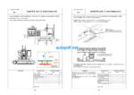
ASSEMBLING PROCEDURES, APPLICABLE EQUIPMENT AND SCHEDULE
KIT LAYOUT DIAGRAM
FLOW OF FIELD ASSEMBLY WORK
TRANSPORTATION
LIST OF FIELD ASSEMBLY TOOLS
TIGHTENING TORQUE
COATING MATERIALS
SELECTION OF WIRE ROPES USED FOR ASSEMBLY
A. ASSEMBLY OF CHASSIS
A-1 Install R.H. and L.H. track frames
A-2 Install travel piping
A-3 Install travel piping covers
A-4 Install steps
A-5 Add grease to swing circle
A-6 Assemble upper structure and undercarriage
A-7 Install R.H. side step
A-8 Install handrails
A-9 Install emergency stop switch on right front step (if equipped)
A-10 Install air cleaner cap
A-11 Install swivel travel piping
A-12 Install L.H. side step
A-13 Install fixed ladder
A-14 Install hydraulic stairway (if equipped)
A-15
Install flash light (if equipped)
A-16 Install L.H. side step emergency stop switch (if equipped)
A-17 Install KomVision camera
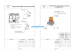
A-18 Install counterweight
A-19 Install counterweight revolving warning lamp (if quipped)
A-20 Install counterweight rear lamp (if equipped)
A-21 Install radiator cover
A-22 Install exhaust tail pipe
A-23 Change installed position of step light
A-24 Change installed position of wireless LAN antenna
A-25 Install operator’s cab revolving warning lamp (if equipped)
A-26 Install operator’s cab handrail
A-27 Install L.H. rearview mirror
A-28 Install R.H. rearview mirror
A-29 Prepare for bleeding air from travel motor
A-30 Bleed air from hydraulic pump section
A-31 Tighten swing circle mounting bolts to specified torque
A-32 Check and adjust track tension
A-33 Check fuel, coolant and oil levels
A-34 Parts to be touched up after field assembly
B. ASSEMBLING OF WORK EQUIPMENT OF BACKHOE
B-1 Release remaining pressure in hydraulic circuit
B-2 Install arm cylinder to boom
B-3 Install arm cylinder hose
B-4 Install boom cylinder to revolving frame
B-5 Install boom cylinder hose
B-6 Bleed air from cylinder
B-7 Install boom foot dust seal
B-8 Install boom assembly
B-9 Install boom cylinder to boom assembly
B-10 Install boom connection hoses (between chassis and boom assembly)
B-11 Install arm assembly
B-12 Install bucket cylinder hoses (between boom and bucket cylinder)
B-13 Install bucket assembly
B-14 Clearance standard for installation of work equipment
B-15 Install work equipment grease piping
B-16 Install work equipment lamps
B-17 Grease after assembling work equipment
B-18 Bleed air from swing motor
B-19 Bleed air from travel motor
B-20 Install travel motor guard
M. PROCEDURE FOR INSPECTION AND MAINTENANCE AFTER COMPLETION ASSEMBLY
M-1 Replace return filter (Replace standard filter → flushing filter)
M-2
Flush hydraulic circuit
M-3 Replace return filter (Replace flushing filter with standard filter)
M-4
Replace pilot filter
M-5 Setting of KomVision (Camera calibration)
M-6 Inspection method of 12 m visibility(KomVision)
M-7 Method for starting up KOMTRAX terminal and default setting of KOMTRAX Plus controller
Field Assembly Inspection Report
Related Category: KOMATSU