
-13%


Format: PDF
Language: EN
File Size: 47.76 MB
Pages: 342
Printable Content
$40 Original price was: $40.$35Current price is: $35.
COVER
FOREWORD
CONTENTS
SPECIFICATIONS
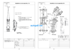
PRECAUTIONS FOR FIELD ASSEMBLY
DISPOSAL OF REMOVED PARTS
ASSEMBLY PROCEDURE, ASSEMBLY EQUIPMENT AND SCHEDULE
FLOWCHART OF MAIN ASSEMBLY PROCEDURE
KIT LAYOUT DIAGRAM
TRANSPORTATION POSTURES
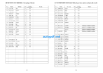
LIST OF PARTS SENT INDIVIDUALLY
TOOLS AND EQUIPMENT TO BE USED FOR LOCAL ASSEMBLY
TIGHTENING TORQUE
COATING MATERIALS LIST
SELECTION OF WIRE ROPES USED FOR ASSEMBLY
SELECTION OF NYLON SLINGS USED FOR ASSEMBLY
A. ASSEMBLY OF CHASSIS
A- 1. Assembly of track frame assembly and center frame assembly
A- 2. Installation of idler cushion cylinder piping
A- 3. Installation of travel motor piping
A- 4. Installation of travel motor cover
A- 5. Filling swing circle with grease
A- 6. Assembly of revolving frame assembly and undercarriage
A- 7. Installation of swing machinery (front) assembly (27t) Installation of swing motor (front) assembly (32t)
A- 8. Connection of swivel joint piping
A- 9. Connection of swing circle grease piping
A-10. Installation of hydraulic tank assembly
A-11. Installation of fuel tank assembly
A-12. Connection of fuel tank assembly piping and wiring
A-13. Installation of cab base assembly
A-14. Installation of emergency escape ladder
A-15. Installation of left floor assembly
A-16. Connection of cab base assembly piping
A-17. Connection of cab base assembly wiring
A-18. Connection of left floor assembly heater piping
A-19. Connection of left floor assembly wiring
A-20. Installation of tail pipe
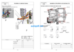
A-21. Installation of power module assembly
A-22. Connection of suction piping
A-23. Connection of oil cooler piping and pump drain piping
A-24. Connection of fan motor drain piping
A-25. Installation of suction unit undercover
A-26. Connection of delivery piping
A-27. Connection of pilot piping and fan motor piping
A-28. Connection of power container assembly fuel piping
A-29. Connection of power container assembly heater piping
A-30. Connection of power container assembly wiring
A-31. Installation of operator’s cab assembly
A-32. Installation of rotary lamp (if equipped)
A-33 Installation of iridium antenna
A-35. Connection of operator’s cab assembly hydraulic piping
A-36. Connection of operator’s cab assembly window washer hose
A-41. Installation of track frame ladder
A-42. Installation of power module side catwalk assemblies (right and left)
A-43. Installation of right floor assembly, grease can cover assembly and center floor
A-44. Installation of fuel tank right catwalk assembly
A-45. Installation of fuel tank front catwalk assembly
A-46. Adjustment of exterior parts clearance
A-47. Connection of grease reel piping
A-48. Installation of access ladder assembly
A-49. Installation of counterweight assembly
A-50. Installation of deformation preventing stoppers for catwalk assemblies (left and right) on the side of power container
A-51. Installation of handrail on counterweight
A-52. Installation of handrail clamps
A-53. Connection of fuel cut wire
A-54. Connection of drain piping under power container
A-55. Connection of battery wiring
A-56. Setting of hydraulic tank strainer
A-57 Replacing standard filter to flushing filter
A-58. Starting engine, checking oil and coolant levels, bleeding air from each part, and adjusting track
A-59. Permanent tightening of swing circle bolt
A-60. Parts to be touched up after field assembly (chassis side)
A-61. Connection of engine heater connection port
A-62. Installation of optional harness
A-63. Installation of KomVision and rear lamp
A-64. Connection of emergency stop switch (if equipped) (at the right below power module)
A-65. Connection of emergency stop switch (if equipped) (at the left side of ladder)
A-66. Installation of engine oil and PTO oil pipings
A-67. Installation of coolant piping
A-68. Installation of guard bracket (if equipped)
C. ASSEMBLY OF BACKHOE
C- 1. Installation of boom cylinder
C- 2. Installation of boom cylinder hoses
C- 3. Assembly of boom sub assembly
C- 4. Installation of boom assembly
C- 5. Installation of boom cylinder head side
C- 6. Installation of hoses between boom and chassis
C- 7. Installation of arm assembly
C- 8. Installation of arm cylinder
C- 9. Connection of hoses between boom and arm
C-10. Connection of auto grease piping
C-11. Connection of wiring between boom and chassis
C-12. Installation of bucket assembly
C-13. Installation of bucket link
C-14. Bleeding air from cylinders
C-15. Parts to be touched up after field assembly (work equipment side)
C-16. Bleeding air from auto grease circuit
LS. ASSEMBLY OF LOADING SHOVEL WORK EQUIPMENT
LS-1 Installation of arm cylinder bottom parts
LS-2 Installation of boom cylinder to machine body
LS-3 Installation of boom cylinder hoses
LS-4 Installation of boom cylinder piping
LS-5 Installation of boom assembly
LS-6 Installation of boom cylinder head pins
LS-7 Installation of hose between machine body and boom
LS-8 Installation of bucket cylinder assembly
LS-9 Installation of arm assembly
LS-10 Installation of arm cylinder assembly
LS-11 Installation of hoses between boom and arm
LS-12 Installation of bucket cylinder hoses
LS-13 Installation of grease feed hose of bucket cylinder
LS-14 Installation of bucket assembly
LS-15 Installation of arm cylinder junction hoses
LS-16 Installation of bottom dump hose and grease feed hose between arm and bucket
LS-17 Installation of arm dump cushion (proximity switch)
M. INSPECTION AND SERVICING PROCEDURES AFTER ASSEMBLY
M- 1. Inspection of oil levels and coolant levels and using standard of fuel and lubricant
M- 2. Flushing of hydraulic circuit
M- 3. Releasing residual pressure from hydraulic circuit
M- 4. Releasing residual pressure from HIC circuit and check of gas pressure in HIC accumulator
M- 5. Charging air conditioner with refrigerant
M- 6. Installed angles of mirrors
M- 7. Installed angles of lights
M-8. Method for starting up KOMTRAX terminal and default setting of KOMTRAX Plus controller
M- 9. Method of camera calibration for KomVision
PC2000-11 Main pump air bleeding check sheet
FIELD ASSEMBLY INSPECTION REPORT (BACKHOE)
FIELD ASSEMBLY INSPECTION REPORT (LOADING SHOVEL)
Related Category: KOMATSU

